Tag: tunnel rail replacement
Making Tunnel Rail Replacement Pieces
by Garage Weasel on May.10, 2021, under Chassis
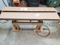
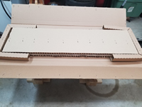
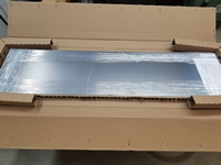
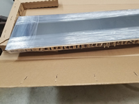
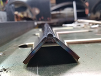
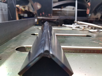
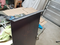
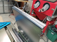
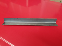
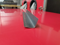
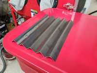
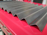
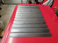
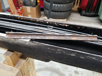
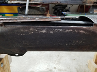
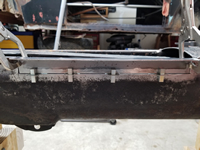
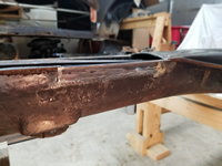
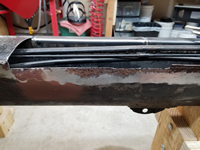
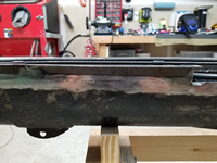
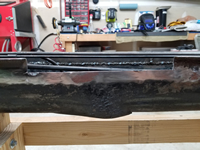
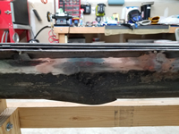
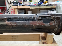
After searching for years for something that I could just purchase to use to replace the rusted-out tunnel rails on my chassis, I decided to just make my own. "Tunnel rail" is what I am calling the lip on the bottom of the tunnel where the tunnel bottom plate is welded and also where the floor pans rest on the tunnel. The closet thing I could find is a 15" tunnel section replacement that is made to replace the tunnel inside of frame heads. But they are around $35 each (plus shipping) and I would need at least 5 of those. Not only would this option be costly, but these aftermarket parts are way thinner metal than the original metal and the shape really doesn't match as well. I found that I could get a 12" x 48" x 2mm sheet of steel online for about $45 total, so I decided to purchase that and see if I could find a way bend it and make pieces to use. It came very well packaged and protected.
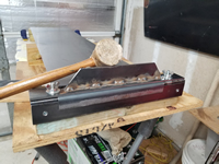
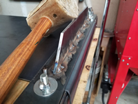
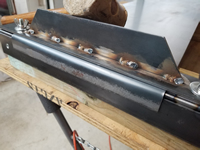
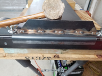
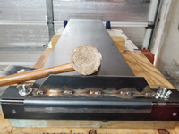
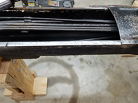
To bend the sheet metal and match the radius of the lip on the tunnel, I used two 18" long, 3/16" thick x 2" wide mild steel plates set at a 90 degree angle with a 1/4" round steel rod on the outer edge and welded them on the inside edge. This gives me a smooth rounded surface on which to pound the metal into shape. The sheet metal is 2mm thick and will take a lot of force to form it.
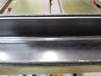
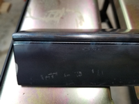
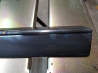
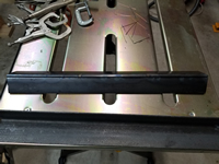
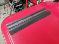
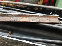
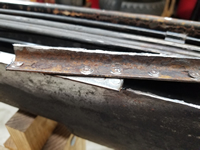
After the plates and dowel were welded together, I made a clamping plate, added clamping bolts, and mounted the unit on a 4" x 4" treated post. The post is dense and heavy and gives me something to hold on to when forming the shape. I used a large rawhide mallet to hammer it into shape. It was quite difficult to bend metal this thick without distorting it and to get it flat and even. With a lot of pounding, I was able to get it fairly flat and checked it against a tunnel section I had from a donor frame head. It matched well. The flange is longer than the tunnel flange, but it gives me more leverage to bend and form it and it can later be trimmed once the tunnel bottom plate is welded back on.
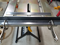
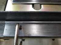
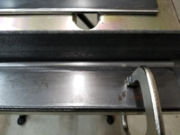
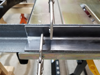
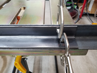
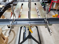
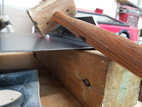
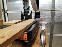
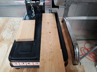
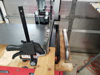
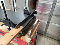
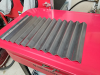
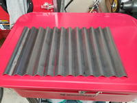
The next issue was how to cut the piece off and to get a nice, straight cut. I can't really do that well with an angle grinder with a cut-off wheel, so I decided to try to do this with my chop saw. I have an Evolution Rage 2 chop saw with a 14" multi-material blade that will cut steel, wood, and plastic. And although the blade is 14" in diameter, it doesn't go down far enough into the table to get a 12" long cut as I needed. So I took the clamping mechanism off of the table and attached a 1" x 4" piece of wood to raise the cutting area up and this made the cutting length about 12 1/4" which is sufficient. I then used some steel plate and 2 clamps to clamp the sheet down while cutting. It was a little difficult to make sure that the cuts were square, but I managed to get them close enough. I checked the first one against the tunnel and it matched well. I made another and it was very close to the first one. I made a few more and the results were good. I went ahead and made 12 of them. Good thing I did as I ended up using 11 of them to complete the tunnel.
Repairing The Tunnel Rail – Passenger Side
by Garage Weasel on May.17, 2021, under Chassis
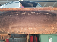
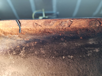
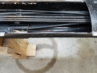
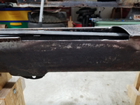
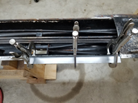
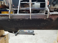
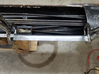
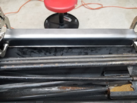
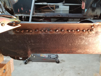
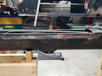
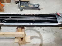
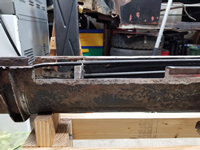
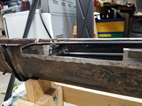
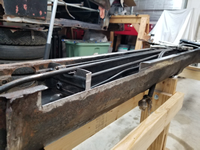
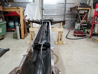
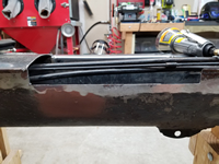
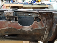
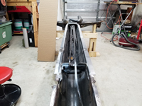
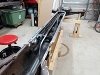
Now that I have the repair pieces made to replace the tunnel rails, it's time to start cutting and welding them in. My plan is to replace the rail from the point that I removed the tunnel bottom plate, all the way to the end in the frame head. I made the pieces long enough on the tunnel side of the pieces to reach past most all of the rust damage. I will have to patch a couple of places where the damage extends upward past them, but these will cover almost all of the damage. I will weld these pieces in on both sides and ground them down on the outside, but leave the welds as is on the inside for strength. They will not be visible and I'm mainly interested in them being strong. I'm starting on the passenger side as it has the least amount of damage and is the least complicated.
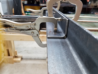
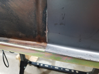
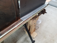
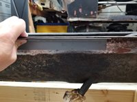
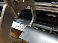
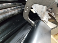
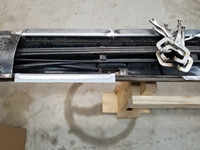
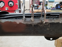
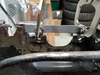
The first section took quite a while to do as I tried different things to figure out the best way to do this. I first laid out a replacement piece on top of the rail, marked the length, and cut 1/2 inch or so through the lip down into the tunnel. After that I cut across between those two cuts to remove the lip. I then placed the piece on the tunnel, lined it up with the existing lip on both ends of the cut-out, and clamped it in place. With it clamped, I then used the piece as a guide to cut through the tunnel. I now had a cut-out just a little larger than the size of the piece. I first held the piece in place for welding using panel clamps, but after just a few tacks across the joint, the panel clamps were locked in tight from the shrinkage of the metal when cooling and I could barely get them out. From that point on, I just used vise grip style clamps. The first three sections were pretty much the same and just involved determining and making the cuts and clamping and welding the pieces in.
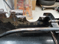
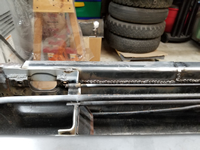
The fourth section on this side connects to a tube support bracket for the clutch tube, fuel line, and choke tube. I drilled a couple of spot weld holes in the piece to attach it to the support brace. Next, I will replace the same four sections on the driver side.
Repairing The Tunnel Rail – Driver Side
by Garage Weasel on May.22, 2021, under Chassis
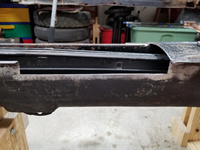
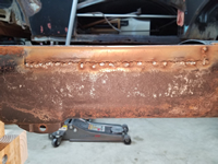
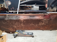
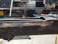
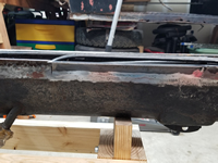
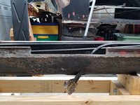
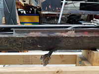
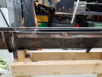
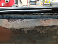
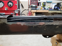
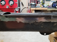
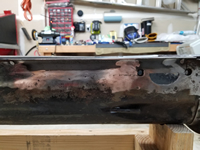
Now on to the driver side of the tunnel to replace the tunnel rail. This side is definitely the worst of the two sides. During the two decades that this car sat outside in the elements, water apparently pooled in the floor pans and there must have been water in higher volume and for a longer period of time on the driver side due to the damage. The tunnel on this side was rusted completely through to the inside in one area and this damage will be cut out on the first and second sections being replaced. In the first section, the cut-out for the piece did not extend high enough to include all of the damage, so I had to make two small patches. I welded them in first and ground down and dressed the welds. I then welded in the first section on both sides and ground down and dressed the welds on the outside.
Next I replaced the second and third sections. The third section had a little area that had a little pitting. Rather that patch it, I ground the area down to clean metal and filled it in with weld. I then welded the section in as usual.
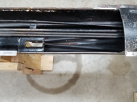
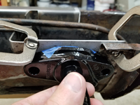
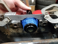
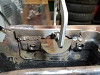
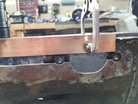
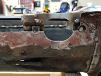
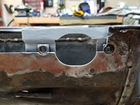
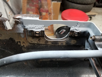
The fourth section includes metal that goes in front of the pedal cluster support plate. Part of that support plate was severely rust damaged, so I first cut out for the tunnel rail replacement piece and then cut it out and welded in a replacement piece on the support plate. I had to grind out an area on that new piece to allow for the pedal cluster mount to fit into the tunnel. I checked it with the already powder coated cluster mount and taped it with tape to protect it from scratches. Once satisfied with the clearance, I welded on the new piece. I used a copper bar behind it as I welded it to keep the weld from blowing out on the edges. I ground down the welds on the outside of the support plate and left the ones on the inside. I drilled holes in the tunnel rail replacement piece to weld to the support plate and then welded the fourth section in. I left the area covering the hole for the pedal cluster mount for now.
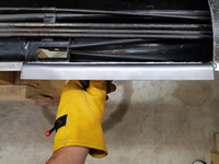
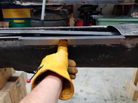
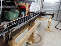
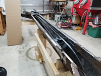
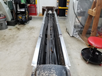
With the fourth section welded in and the welds ground down and dressed on the outside, I now had four feet of tunnel rail replaced on both sides. Next up is to continue and finish the tunnel rail replacement through the frame head and up to the frame head front plate.
