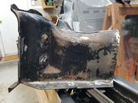
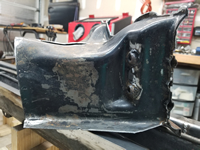
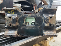
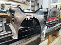
Welding the Tunnel Bottom Plate
by Garage Weasel on Apr.30, 2024, under Chassis
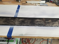
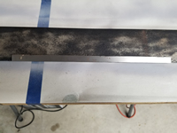
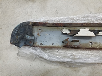
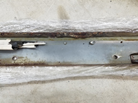
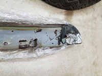
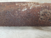
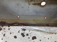
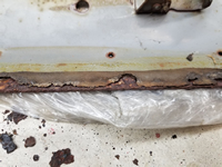
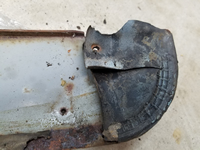
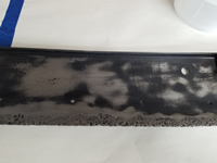
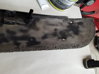
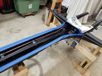
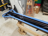
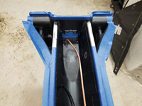
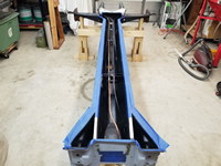
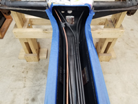
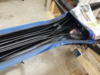
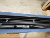
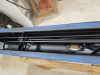
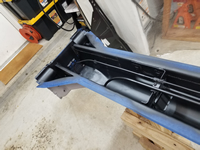
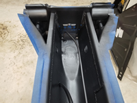
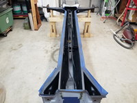
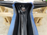
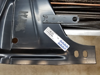
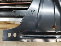
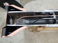
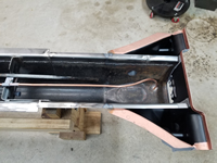
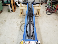
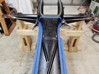
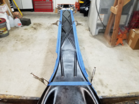
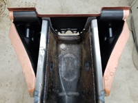
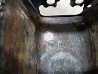
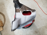
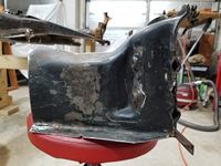
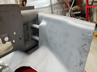
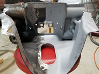
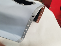
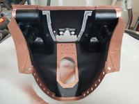
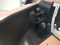
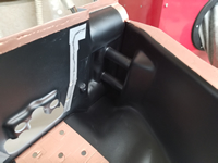
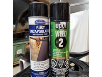
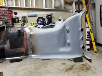
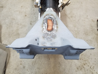
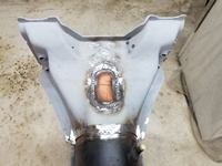
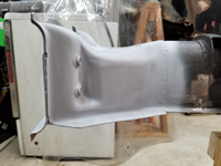
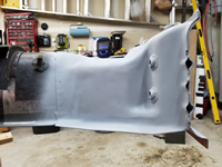
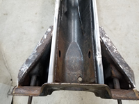
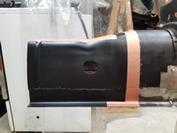
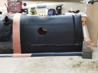
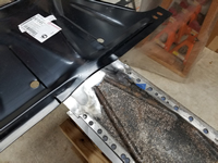
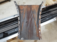
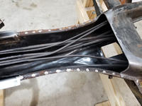
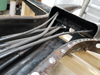
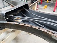
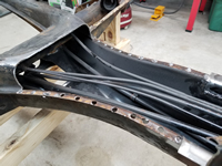
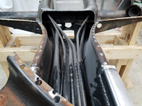
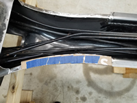
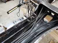
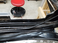
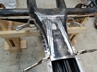
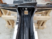
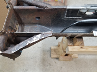
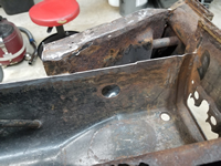
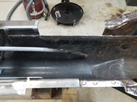
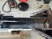
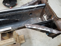
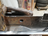
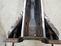
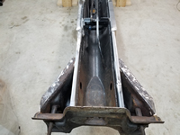
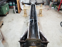
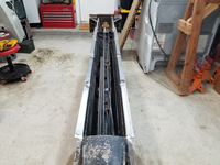
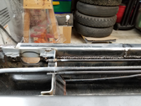
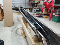
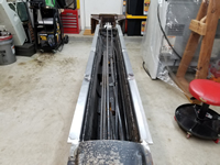
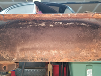
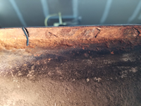
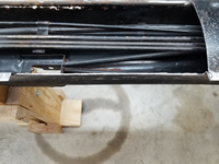
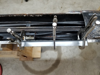
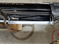
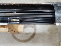
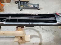
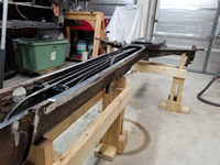
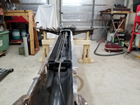
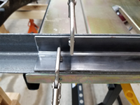
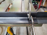
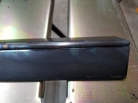
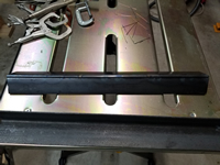
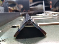
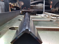
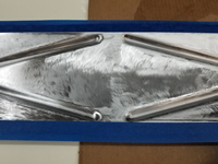
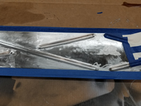
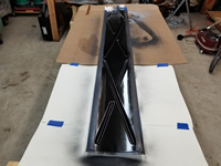
I'm finally at the point that I can weld the tunnel bottom plate back on. First, I touched up the protective coating on the inside of the tunnel with Eastwood Matte Black Rust Encapsulator. Then, I cleaned up the areas where it will be welded.
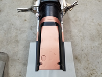
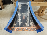
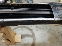
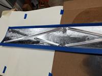
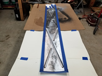
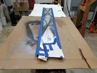
Next, I masked off all areas where the panels will fit together and sprayed them with U-POL Weld #2 Copper Weld Through Primer.
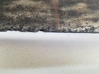
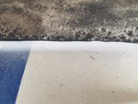
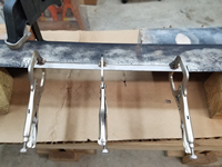
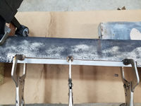
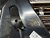
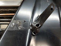
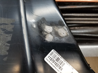
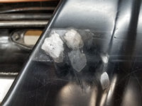
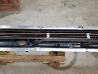
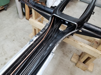
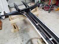
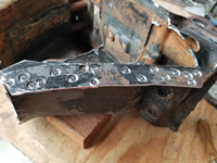
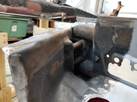
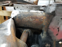
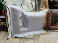
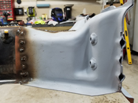
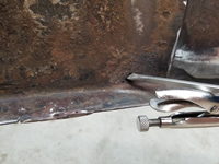
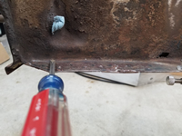
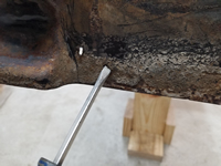
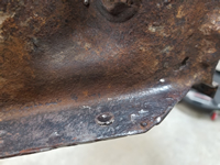
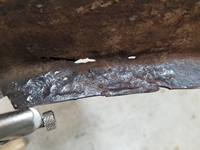
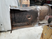
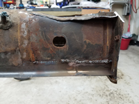
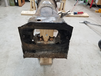
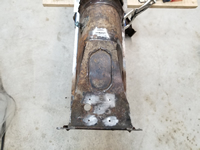
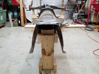
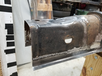
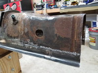
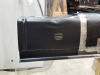
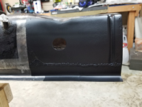
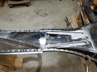
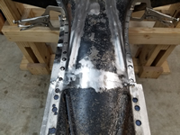
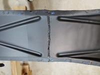
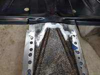
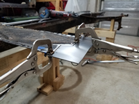
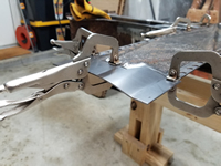
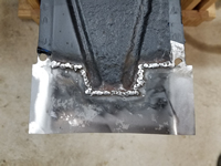
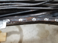
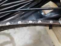
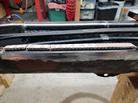
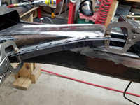
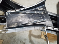
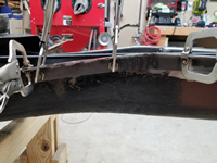
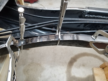
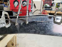
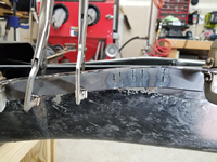
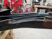
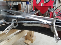
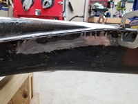
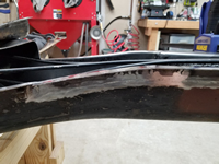
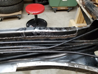
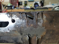
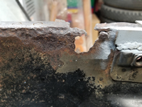
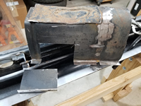
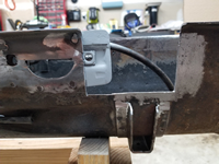
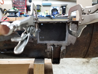
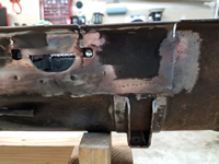
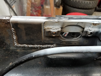
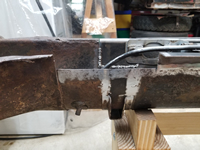
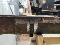
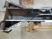
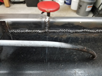
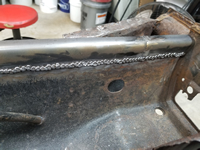
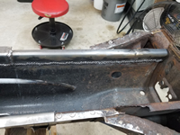
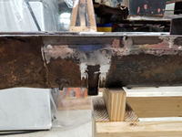
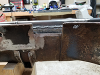
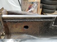
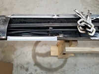
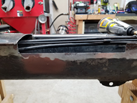
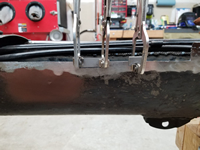
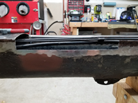
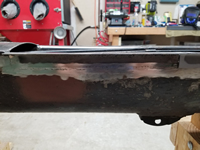
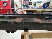
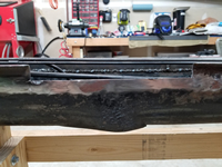
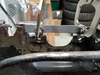
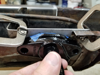
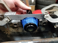
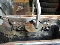
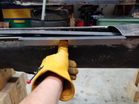
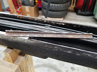
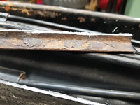
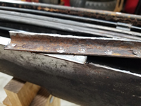
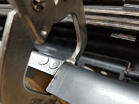
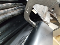
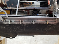
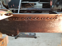
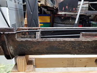
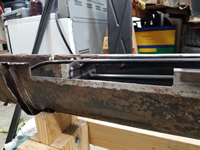
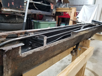
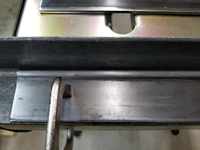
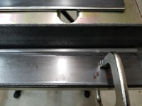
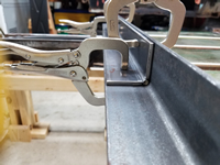
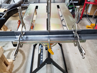
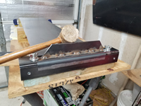
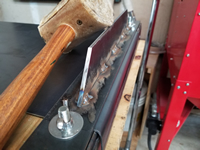
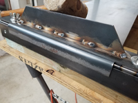
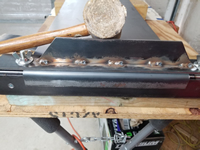
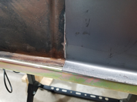
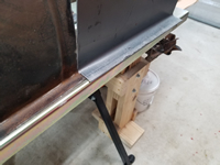
It's been a while since I last welded and I had to buy a new welder, so I really didn't know how this was going to turn out. I started by welding the welds on either side of where I had placed the sheet metal screws. There was a steep learning curve to overcome. The holes that were created with the spot weld cutter were huge (3/8"), and many were very close to the edge of the plate. Getting the welds hot enough to penetrate the 2-milimeter plate and fill the holes without melting away the thin outer edge was very difficult. Fortunately, the replacement rails were quite a bit wider so if the welds did melt the outer edge away and spill over, it shouldn't really cause an issue as the rails will be trimmed back when I fit the floor pans. Out of curiosity, I counted the welds on each side - 63 on the driver side and 76 on the passenger side. I took my time and made sure that I didn't get the metal get very hot. After doing all of the spot welds, I ran a straight bead on the rear seam where I had cut the bottom plate. I received mixed results, but I did get it done. Lots of grinding ahead!
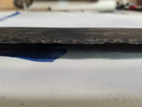
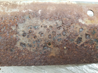
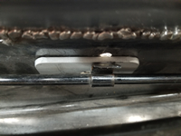
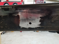
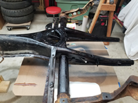
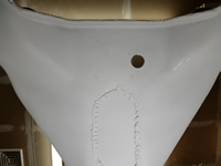
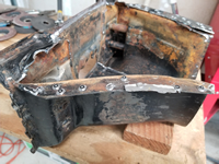
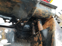
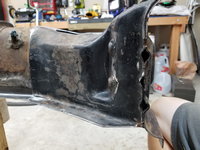
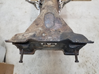
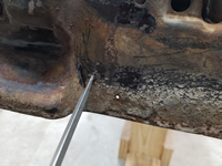
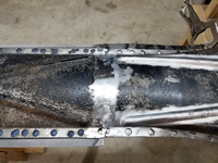
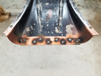
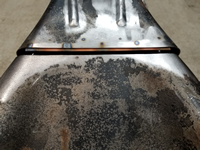
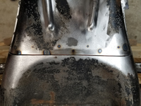
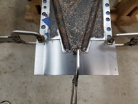
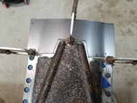
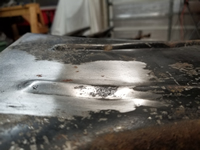
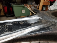
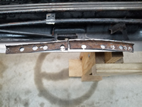
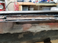
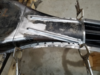
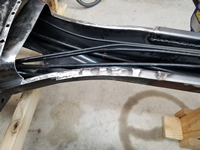
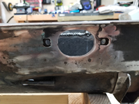
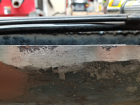
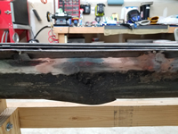
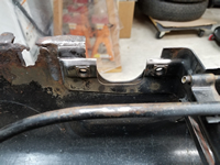
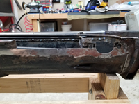
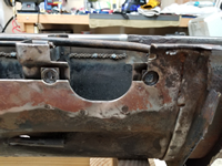
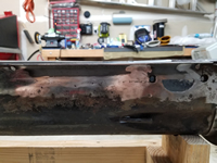
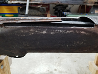
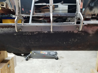
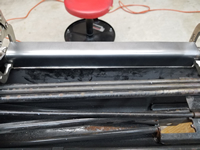
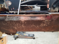
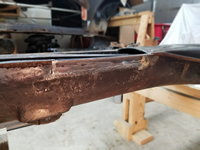
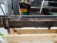
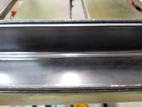
I flipped the chassis over to check the penetration of the welds. I was pleasantly surprised how well they had penetrated. I wasn't able to get this level of penetration with my last welder despite the settings.
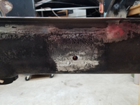
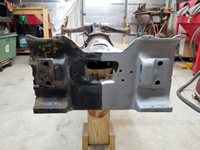
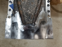
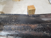
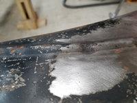
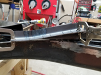
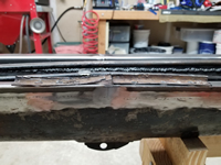
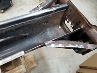
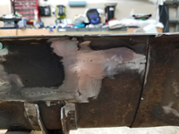
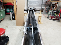
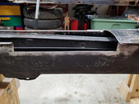
Grinding down the welds took hours, but the welds were solid throughout and I only had to do a few touch-ups. I was able to get it fairly flat and even and felt good about it after it was done. After years of not getting anything done on this car, this felt like a big step in progress.
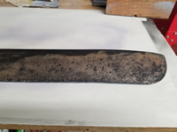
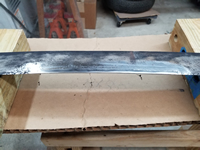
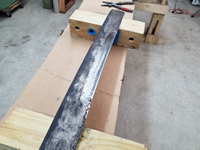
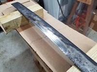
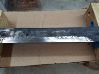
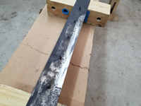
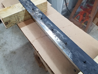
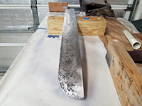
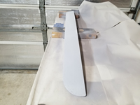
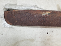
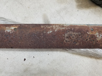
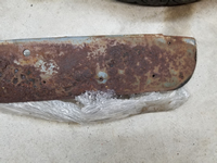
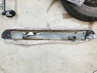
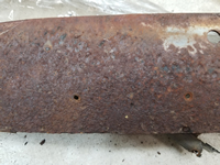
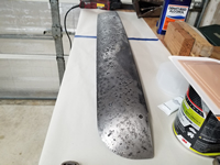
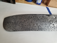
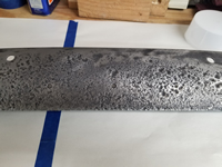
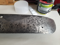
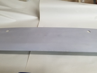
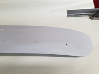
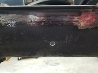
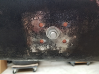
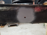
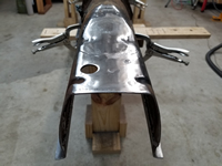
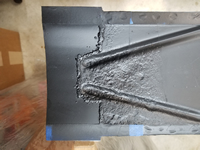
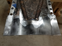
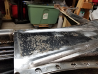
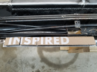
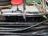
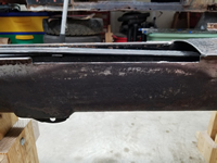
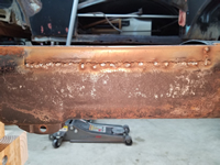
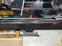
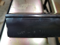
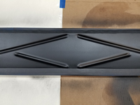
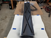
I used a Scotch-Brite™ Clean and Strip XT Pro Disc to remove any remaining paint, rust, undercoating, and mill scale on the bottom plate. These discs do an excellent job and remove very little metal. They are by far the best thing for removing mill scale.
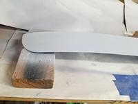
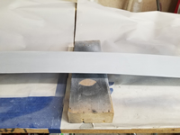
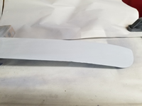
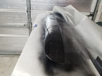
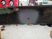
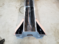
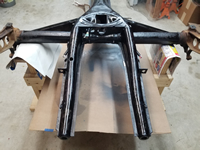
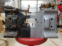
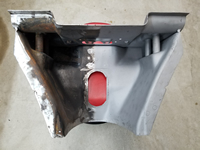
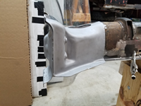
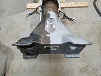
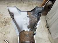
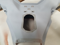
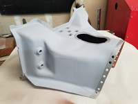
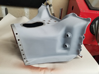
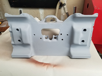
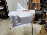
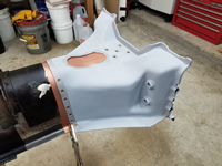
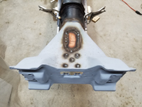
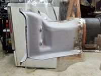
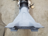
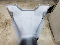
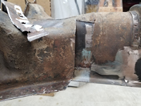
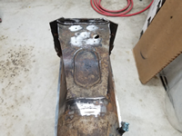
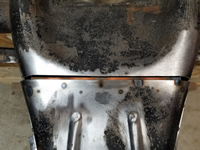
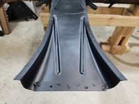
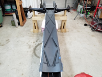
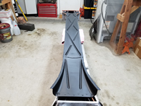
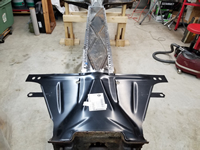
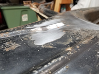
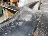
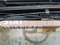
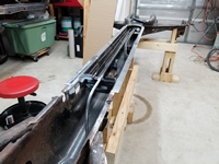
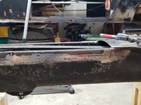
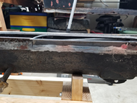
I then sprayed primer over the bottom plate to keep it protected until I get to the paint prep stage. Quite a change from the rust-eaten tunnel I started with!
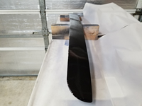
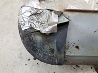
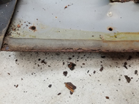
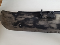
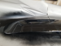
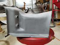
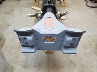
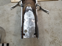
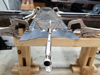
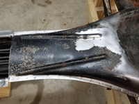
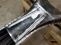
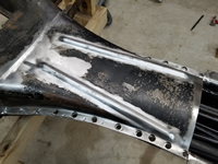
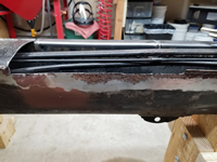
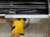
I also used the clean and strip disc on the area where I replaced the tunnel rails and sprayed primer over it.
Next step - welding on the frame head bottom plate.
Back on the Chassis!
by Garage Weasel on Apr.16, 2024, under Chassis
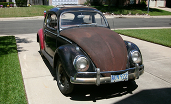
After a three year hiatus, I am finally back to working on this car and more specifically, the chassis. The shop is still in disarray after building out the interior, but it is done enough that I can get back to work on the 1960. This is also the parking spot for my 1973 Super Beetle that can be seen in the background of my images.
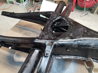
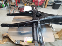
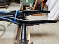
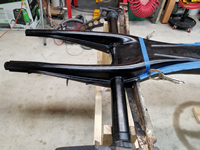
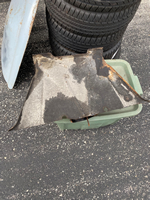
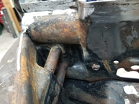
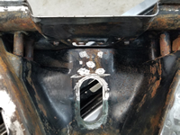
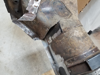
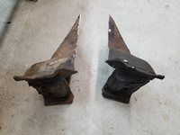
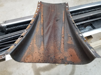
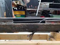
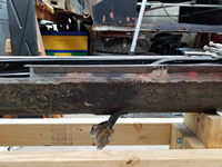
When I moved to my current location two years ago, I fastened the tunnel bottom plate down to the tunnel with self-tapping sheet metal screws to strengthen it and make it easier to move. It's been in this state until now and has been lying around in the shop. When I pulled the bottom plate back off to get started, I found that mice had been inside of it. But fortunately, they didn't cause any issues other than some poop and acorn shells. The protective coating that I sprayed on the inside also kept it them from causing any rust or other damage. I cleaned and disinfected all surfaces. I test fit the frame head bottom plate and the Napoleon hat just to refresh my memory. It will need a lot of fettling to get the pieces fitting well. The frame head bottom plate is a modern aftermarket part and is quite a bit different than the original. The Napoleon hat is a donor part from a mid-1960's Beetle and is very close to the original.
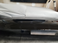
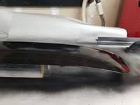
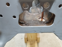
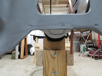
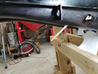
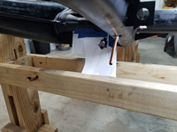
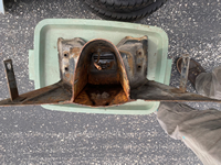
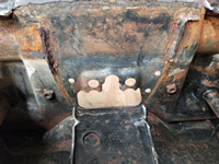
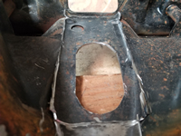
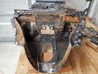
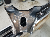
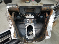
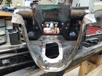
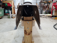
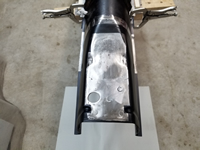
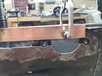
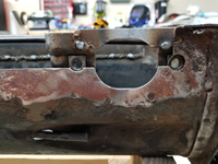
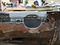
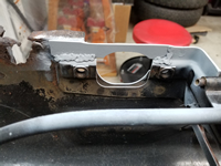
I took a couple of pics from the underside to show the fit of the tunnel bottom plate and Napoleon hat.
The next step is to weld the tunnel bottom plate back onto the tunnel.
Repairing & Repainting The Ragtop Upper Rear Tensioning Strip
by Garage Weasel on Aug.06, 2021, under General
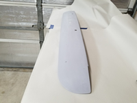
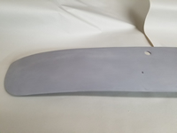
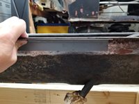
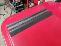
The rear portion of the ragtop is attached to the roof by the upper and lower rear tensioning strips. The ragtop material is tucked under the upper rear tensioning strip and then the 9 bolts on the bottom side of the upper tensioning strip are placed through 9 holes towards the rear of the roof. On the underside of the roof, the lower rear tensioning strip is place over those same 9 bolts and then is secured with 9 nuts and 9 washers. The holes in the roof are slotted, so there is small amount of forward or backward adjustability to tighten or loose the ragtop.
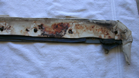
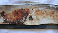
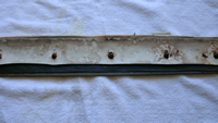
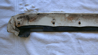
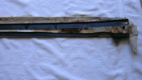
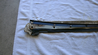
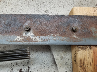
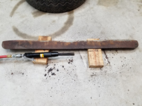
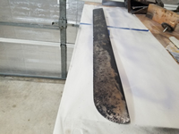
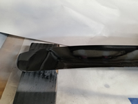
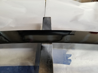
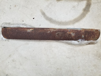
The pictures below show that there were still remnants of the ragtop material still covering the top of the upper rear tensioning strip. The lower rear tensioning strip is shown as well. After the ragtop material was removed, thick crusty rust was revealed. Also, one of the bolts snapped off during the removal of the upper strip and will need to be replaced. This will require welding one on.
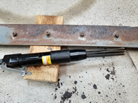
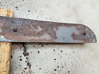
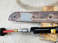
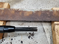
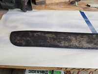
To remove the layers of built-up rust, I first used a pneumatic needle scaler. This did a really good job of removing this type of rust. I put the nuts on the bolts to protect the threads from being damaged. The needle scaler knocked the built-up rust off and revealed the deep pitting that was under it. There was still a lot of rust left, but it was surface rust. To remove this, I soaked the whole piece in Evapo-Rust. This took many days to get it down to the good metal. I then sprayed it with a rust converter, which turns the converted rust black. It can now be coated by filler for the pits, and then with primer and paint.
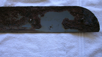
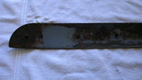
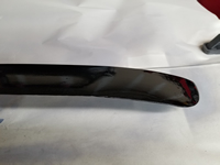
With the rust removed and treated, this also revealed that the back edge of the tensioning strip was very sharp and jagged through the center section. This back edge is where the ragtop material is wrapped around, and it just cannot be sharp as it will cut through the material. I cut a piece of 2-millimeter-thick steel plate to cover this sharp area, cut out the damaged area, and then welded it in. Once ground down, it was ready to be covered and protected. I did also replace the broken bolt but failed to take a picture of it.
I used a flexible body filler to fill in the pits and covered the entire surface area on both the top and the bottom. I sanded it smooth but didn't spend a lot of time on getting it perfect. It will be completely covered and will not be seen once the ragtop is installed. Next, I sprayed on two of coats of primer and two coats of Eastwood Extreme Chassis Black.
Repairing & Painting The Ragtop Upper Header Bow
by Garage Weasel on Jul.22, 2021, under General
When I first disassembled the car, I wrapped most of the larger parts in plastic wrap and placed the largest ones in the attic. Last year, I decided to bring the ragtop parts back into the shop and work on them. I cleaned up, sandblasted, and powder coated many the smaller parts, but just hung the longer parts up in the shop. I did a little work on these parts like removing the rust and treating the really rusted parts with a rust capsulator. After that, I moved on to other things and the parts remained hanging there for nearly a year. Tiring of having things hanging and in the way, I went to work to get them completed. I started with the upper header bow. This part is on the top of the front of the ragtop. It goes directly over the locking bow that has the handle that you use to open, close, and lock the ragtop. The outer part of the ragtop cover tucks under it in the front and it is the part that clamps down on the roof when the handle is locked.
Below is what the upper header bow looked like when I unwrapped in from the plastic wrap. It was very rusty from being wet all those years and even where there were still parts of the ragtop cover on it, it still got wet and stayed wet for a very long time. On the leading edge of the bow, it had a foam strip where it made contact with the roof. Water apparently seeped under there as well and the bottom side under that foam strip suffered the same rusting and pitting that the exposed top side did.
To remove the rust, I had to soak this piece for about a week in Evapo-Rust. This product does not remove the base metal and only removes the rust. I would soak it for a day or so and then rinse it off to remove any loose rust particles and put it back in. Once it had removed all the loose rust, I sandblasted it. There was still some minute rust particles down in the pits, so I sprayed it with a rust converter to seal those areas. I let that cure and then this is the condition I left it in a year ago.
Since this is going to be covered by the ragtop cover, I decided to fill in the pits with body filler and paint it. I filled in the pits, sanded it smooth, sprayed it with primer, and then sprayed it with Eastwood Extreme Chassis Black. I think this will seal it up and protect it fairly well. It is a little wavvy, but it will be under the ragtop cover and not seen.
Protecting Inside Of Tunnel
by Garage Weasel on Jul.18, 2021, under Chassis
Before welding on the bottom plates for the tunnel and frame head, I wanted to get a good protective coating on the inside components. I masked off the areas where the plates would be welded and sprayed the inside areas with Eastwood Matte Black Rust Encapsulator. This should help protect the inside for many years to come.
Making And Installing Seatbelt Mounts on Tunnel
by Garage Weasel on Jul.12, 2021, under Chassis
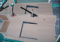
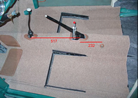
Being a 1960 model, this car did not come with seatbelts and didn't even have seatbelt mounts installed at the factory. I want to install seatbelts in this car, so I am going to add mounts in the factory locations. Since I am working on the chassis now, I need to add mounts on the tunnel. I don't have any information on exactly where these need to be installed, but I found a couple of pictures in the Internet of mid-1960 models with the factory mount locations. With these pictures, I needed to determine these locations by using some reference of a known quantity. I was able to determine that the measurement from the center of the stick shift hole in the tunnel to the center of the emergency brake pivot pin is about 475mm. So on the picture I had, I drew a line from the stick shift center hole to the emergency pivot pin center which according to the image editing software was 517 pixels. I drew another line on the picture from the emergency brake pivot pin center to the center of the bolt on the seatbelt location, which was 232 pixels. So with these measurements I was able to come up with an equation of 517/475 = 232/x. Solving for x gave me 213.15mm. So I rounded up to 214mm. This should get me in the ballpark of the correct location of the two mounts on the tunnel if I use the emergency brake pivot pin center and measure 214mm towards the back of the tunnel.
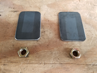
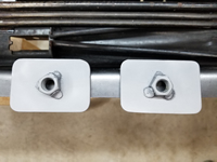
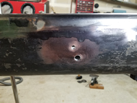
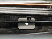
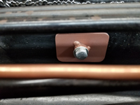
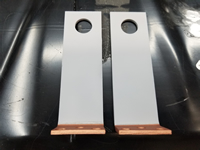
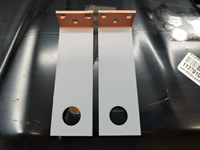
To make the mounts, I took two 2" x 3" pieces of 3/16" steel, drilled 1/2" holes in the centers, curved them slightly so that they would fit the contour on the inside of the tunnel, and welded two 7/16-20 nuts on them. I then sandblasted them and gave them a coat of copper enriched weld-through primer just to protect the bare metal. Next, I measured 214mm from the emergency brake pivot pin center towards the back of the tunnel and for the location vertically, I just eyed it and guessed. Not a very scientific method, but I think I will be close enough. At those locations, I drilled 1/2" holes in the tunnel for the seatbelt bolts and four holes for spot welds and welded the mounts to it. The driver side was a challenge as the mount location just happened to be right where one of the accelerator tube mounting brackets was welded to the tunnel. So I drilled out the spot weld on that bracket, welded up in the hole I just drilled in the tunnel, and bent the tube out enough to clear the mount. I then welded the bracket to the mount. I'm almost done with the work inside the tunnel. I just need to weld the new frame head front plate to the end of the tunnel and then I can start fitting the frame head bottom plate to the frame head, tunnel bottom plate, and the Napoleon hat.
Removing Brake Hose Bracket On Replacement Frame Head Bottom Plate
by Garage Weasel on Jul.05, 2021, under Chassis
The aftermarket frame head bottom plates come with a flimsy, thin brake hose bracket that has to be bent up into position. This makes it a little short and does not match the original brackets in appearance, the point where it is welded on, nor in strength. I decided to remove these and also remove the ones on the donor frame head to use instead. I sandblasted the donor brackets, sprayed them with primer, and also sprayed the areas to be welded with weld-through primer. I will install them later once the welding for the bottom plates, the Napoleon hat, and the floor pans are done.
Replacing The Fuel Line In The Chassis
by Garage Weasel on Jul.01, 2021, under Chassis
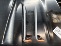
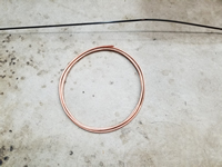
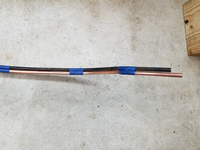
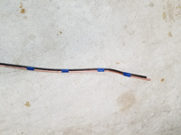
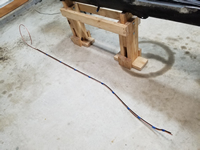
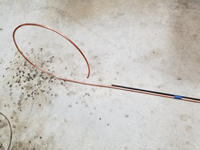
I purchased a 10' coil of 6mm OD (4mm ID) tubing to replace the original fuel line that runs through the chassis. It was corroded and damaged inside the tunnel and needed to be replaced. I used the original line as a pattern to bend it to the proper shape to fit. It was quite a challenge to make something coiled up match something that had mostly straight runs. I started on one end and once I had around 8" of a section matching, I taped it to the pattern and continued that until I got to the end of the old line. I had previously cut the frame head end of the line off to make it easier to repair this end of the tunnel, so I didn't have a pattern to follow for the rest of it. I used an old picture as a reference to determine the original shape. The bends here have to be clear of the installation and removal of the shift rod that goes from the shift lever to the transmission. Before I weld the bottom plates back on and close up the tunnel, I will have to check that the shift rod can be easily installed and removed. When I removed it when disassembling the chassis, it was very difficult to remove. I'm not sure why.
The original line was crimped into the spacers that mount the various tubes inside the tunnel. The only way to remove it was to to cut off the part of the spacers that were holding it. Fortunately, it was on the end of each of the three spacers and was easily cut off. I made new holders and then drilled and tapped them so that I could mount them to the spacers. I crimped the holders down until they were snug and will later put some rubberized caulking on them to keep the tube from rattling in the holders. I also put Loctite on the screws securing the holders to the spacers. I put silicone tubing over the last foot or so of the line where it feeds through the forked area to keep it from rattling where it contacts another tube and the inside of the fork. I then fished a copper wire through the fork into the tunnel and then taped it to the line so that I could pull it through the fork.
Note: When done, I had 18" left over from this 10' copper coil.
A Little Rust Treatment On The Chassis
by Garage Weasel on Jun.29, 2021, under Chassis
Before I flip the chassis over to weld on the bottom plates and replace the fuel line, I decided to treat some of the rust on the forked rear area. I used steel brushes in my drill to remove the loose rust, wiped the areas down with a degreaser, and then sprayed the areas with Eastwood Rust Converter. It's actually still curing and wet in the below pictures. This product seals in rust and will protect it until I get to prepping for paint. I didn't do the shock arms just yet as I need to purchase different steel brushes that will get into the recesses better than what I currently have. I also didn't do much with the cross member/floor pan supports as they will be replaced with the floor pans. I just sprayed the rust converter on it without removing loose rust.
Once the rust encapsulator cured, I flipped the chassis over and treated the same areas on the bottom side as well as the tunnel bottom plate. I masked off the areas where I will be welding. It is very pleasing to see the bulk of the chassis cleaned up and uniform in finish. I had a little feeling of accomplishment with this done. I did go back after taking the pictures and spray rust encapsulator on the cross member/floor pan supports.
I also remembered that I needed to drill a hole in the frame head for the fuel line to exit through. The 1963 frame head replacement didn't have the hole on top in the same location as the 1960 models. It had a hole inside the oval area on top. From here, it connects to the fuel tank. For reference, it is a 15mm hole.
Updates – Finally!
by Garage Weasel on Jun.28, 2021, under General
I have had a dilemma for a while now. I have been doing work on the car, but have not been updating the site with the progress. Well today, I decided to start updating the site with the current work I am doing and then work backwards to add the previous work until I fill in the gaps. I will backdate the posts so that they will show in chronological order as they are added. It's a start!
Disassembling, Preparing, and Welding On Donor Frame Head #2
by Garage Weasel on Jun.25, 2021, under Chassis
Over time, I realized that the first donor frame head was just too different to use on my chassis. It is from a 1965 and is a slightly different design than mine. It's close, but I would have to alter the pieces of it I intended to use too much and would make the replacement more complicated than it needed to be. I found a really solid 1963 one for sale in thesamba.com classified ads and purchased it. It was an exact match. It arrived in great condition and was very well packaged for protection from shipping damage. In fact, it was by far the best packing job I've ever seen. These are the pictures that I received from the seller before I purchased it:
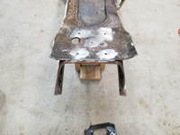
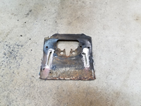
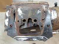
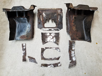
After much consideration, I decided to use the outer portion and front plate of this frame head and removed the tunnel and bottom plate portions. I removed large areas of both to make it easier to remove the areas that were spot and seam welded. I included a picture below that shows all the pieces that had to be removed.
Here's what it looked like after everything was removed:
I then cleaned it in the parts cleaner, briefly soaked it in rust remover to loosen up the rust, and then lightly sandblasted half of it just to see what it would look like. I was very pleased! It is very solid metal with only a slight bit of pitting. Overall, it is a much better thickness of metal than an aftermarket part and almost identical to my original.
I placed the new part on the tunnel to check the fit and was surprised how well it fit. On the top, it fit very well and was sprung outward on the bottom sides a little, but was easily clamped down for a very snug fit all around.
Next, I sandblasted the entire part, sprayed primer on the outside of it, masked off and sprayed U-POL Weld #2 Copper Weld Through Primer on the inside areas that are going to be welded, and sprayed Eastwood Matte Black Rust Encapsulator on all other areas on the inside that are not going to be welded.
One final check of the fit before welding on.
Welding time! I welded the donor frame head part on and dressed the welds. Most of them will be covered by seam sealer, so appearance isn't all that critical. After many years just thinking about how I has going to accomplish this, this part is finally done. If I can give one piece of advice to anyone out there doing a restoration - just get started and don't be afraid to make mistakes. You will likely make mistakes, but at least you are making progress. Half of the challenge is undoing what you've messed up. Progress beats procrastination every time.
I sprayed some primer over the bare areas that were just welded to protect it until I start to prep for paint. Now it's time to flip it back over to install the new fuel line and to weld the bottom plates on the new frame head and the tunnel.
Removing The Frame Head To Prepare for New Donor Replacement
by Garage Weasel on Jun.13, 2021, under Chassis
Time to remove the frame head and prepare the tunnel for the new donor frame head section. The original frame head is just too rusted on the bottom inch or so and is super thin and pitted. From the top, it doesn't look that bad. But an examination of the bottom sections shows severe rust damage. For a long time I considered just cutting out the bottom areas and welding in sections from a solid frame head, but finally realized that if I had a solid one or the relavant part of one, I should replace the bulk of it and have a stronger frame head overall. Here are examples of the rust damage:
I started removing the old frame head piece by grinding down the spot welds where it wraps around the tunnel. Once the spot welds were ground down, I cut through the frame head so that I could peel the metal back and then off. I did this on both sides and then cut through the area on top of the tunnel where it was seam welded. Next, I cut through the top toward the front plate and then down through the front plate to remove the areas on the sides to expose the tunnel. Big chunks were removed this way and this just leaves the piece on the top and the middle of the front plate. I then ground through the front plate where it is welded and removed it. Lastly, I ground through the oval-shaped seam weld on the top piece and then used a spot weld cutter to remove the 5 spot welds as well. These spot welds are in an X pattern. I also included a picture of all the items removed below.
I cleaned up the areas where the frame head was welded to the tunnel, but still need to complete the seam welds on the outside of the tunnel where I couldn't access them due to the frame head covering them up. I just feel better having it welded on both sides. I will ground them down where the new frame head will contact the tunnel. On the passenger side of the tunnel there is one area that is a little pitted and instead of cutting it out and patching it, I will remove the rust and build the area up with weld. It's not quite bad enough to cut out and replace.
I finished the welds on the outside of the tunnel and ground them down where the frame head contacts the tunnel. And then I wire-wheeled the ouside of the tunnel to remove any paint and rust, wiped it down with a degreaser, and then sprayed the areas that are not going to be welded with Eastwood Matte Black Rust Encapsulator. These areas are going to be hard to get to and protect once the frame head is welded on and I want to make sure that they are protected and sealed. The areas that are going to be welded were sprayed with U-POL Weld #2 Copper Weld Through Primer. It's now ready for the new frame head!
Welding The Tunnel Bottom Plates Together
by Garage Weasel on Jun.04, 2021, under Chassis
I decided to weld the straight section of the tunnel bottom plate to the additional bottom plate section that I removed and make them one piece. The reason is that I can get an overall better welded joint as I can weld on both sides. I did that and also added a connecting plate on the wide end. This helps to hold this end in place and also gives me an additional layer to weld to and strengthen that joint. I sprayed the connecting plate and the area under it on the bottom plate with U-POL Weld #2 Copper Weld Through Primer.
Next, I ground down the welds on the outside and then sprayed the inside areas that will not be welded on with Eastwood Matte Black Rust Encapsulator to seal and protect them.
After the rust encapsulator cured, I place the bottom plate back on the tunnel and then checked the fit of the frame head bottom plate with it. At least in this area, the frame head bottom plate fits well. In other areas, not so much. That's a problem for later.
Repairing Straight Section of Tunnel Bottom Plate
by Garage Weasel on Jun.02, 2021, under Chassis
On the frame head end of the tunnel bottom plate, there was severe rust damage and it was actually rusted through. The only way to repair this is to cut out the damaged area and weld a new piece in. As far as I know, there are no repair panels readily available. In fact, I only know of one source in Finland and I don't want to wait that long or spend that much for a complete panel as I really only need a few inches of it replaced. So I decided to just cut out as much of the flat areas out as necessary and retain the raised portions of it, which would be difficult to reproduce. I started with piece of 2mm plate that I had left over after making the piece for the tunnel rails. I used the jig that I made for the tunnel rails to hammer the straight crease on the sides where it is flat and bent the domed area basically by hand. I managed to get it to match closely to the tunnel bottom plate. It took quite a while and was very difficult to match the shape. Once I was satisfied with the shape, I cut the needed flat areas out of the tunnel plate and then cut the new repair piece to match it. It's a bit off in the pictures below, but I did adjust the fit to be more uniform throughout the joint. I welded it on both sides, ground down and dressed the welds on the outside of it. I will trim the excess width off of it later when fitting and welding the tunnel bottom plate back on the tunnel.
Removing/Repairing Additional Tunnel Bottom Plate Section
by Garage Weasel on May.31, 2021, under Chassis
I thought long and hard about removing this additional section of the tunnel bottom plate. I knew it would be a lot more work, but finally decided that I needed to for 2 reasons. The first reason is that I need to replace some more tunnel rail on the driver side. The problem with replacing this section is that it both curves out and down and is way more complicated than the straight sections I already replaced. The second reason is that this section is dented in and I have not come up with a valid method of removing those dents without removing it. I thought about using a slide hammer, but I don't think that I could do a satisfactory job that way. So out came the angle grinder with a cut-off wheel and the spot weld cutter. After cutting out 25 spot welds and one foot-long cut across the tunnel, this section has been removed.
I first tackled the dented areas. The dents were mainly in the raised ridges, so I thought that if I could raise these back up and get them straight again that maybe that would bring the surrounding metal back up with it. I used a body panel hammer with a wide, narrow tip, a big rawhide hammer, and a 4" x 4" scrap of wood to use as an anvil and hammered them back straight. This brought the flat areas around them back up as well. This actually turned out better than I had hoped. Next, the hard part.
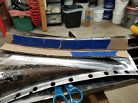
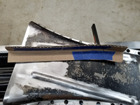
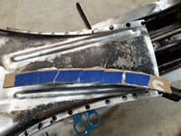
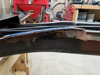
I cut a pattern out of cardboard that was the same size as the rail replacement that I was going to use and bent it to match. Then I cut slits in the cardboard so that I could bend it to match the contour of the tunnel rail area. Each time I got the correct bend, I would tape over the cut to hold it in place. I continued this until I had the pattern matching the tunnel. When I was satisfied with the shape, I removed the tape and laid the pattern over the rail replacement. Each place that there was a slit in the cardboard, I scribed a line on the piece to mark where I needed to cut slits in it. I cut the slits one at a time, bent it, checked the fit, and then tack-welded the slit to hold it in place. I did this for all of the cuts. Of course, the welding process distorted the shape a little and I had to re-cut and adjust it a little. I did finally get it to match fairly well.
With the replacement part now ready, I cut the lip off of the tunnel so that I could match up the top flanges and know where to cut the out the rest of the tunnel to match the replacement. I clamped it to the tunnel and used the edge as a guide for the cut-off disk just like I did with the straight areas. I used smaller cut-off wheels so that I could make the curved cut without cutting out too much. I welded it in on both sides and then ground down and dressed the welds on the outside. I placed the bottom plate section on and checked the fit. Some of the spot welds that I cut out were really far in from the edge and miss the lip of the rail. I will probably fill those area in while the plate is still off of the tunnel as that will be much easier when I can get to both sides of the plate and I can also clamp a copper bar behind it and fill them in.
Completing The Tunnel Rail Repair
by Garage Weasel on May.27, 2021, under Chassis
Before I can continue replacing the rest of the tunnel rail, I need to patch a rusted out area on the driver side under where the Napoleon hat mounts. This damage also extends to the metal in front of the pedal cluster support plate. Rather than make a patch, I cut a section out of the tunnel from the first donor frame head. This matched perfectly. I cut out the tunnel to match the patch, drilled out several spot weld holes for the support plate, and welded the patch in on both sides. I then ground down and dressed the welds on the outside of the tunnel.
On the passenger side, I cut out the rest of the tunnel rail out up to the front plate of the frame head. With that area cut out, you can really see the severe rust damage on the frame head. This section is longer than the frame rail pieces that I made, so I had to use part of another one and weld them together. Then I welded the piece in completely on the inside and as much as I could access on the outside. With the frame head in the way, I could only get to about 2/3 of it. I will complete the rest of outside welds when the frame head is removed. I ground down and dressed the welds on the outside on the short section from the last section welded in up to the frame head.
This section of the driver side is shorter than the frame rail pieces that I made, due to the patch under the Napoleon hat and I was able to use the leftover piece from the passenger side. The cut-out on this section also exposes the rust damage to the frame head on this side. Just like on the passenger side, I welded this section completely on the inside of the tunnel and what was accessible on the outside. I will complete the outside as well once the frame head is removed. I also cut out the rest of the hole for the pedal cluster. I had a real sense of accomplishment with getting these 10' of tunnel rail replaced. I have once more section to replace on the curved portion of the driver side, but that will be in another post.
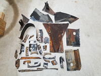
Below are pictures most of the metal cut out to replace the tunnel rail on both sides. I did use some of the better metal to make a couple of patches, this is the bulk of it. Since I took these pictures later, there are pieces included of the curved section that I cut out on the driver side.
Repairing The Tunnel Rail – Driver Side
by Garage Weasel on May.22, 2021, under Chassis
Now on to the driver side of the tunnel to replace the tunnel rail. This side is definitely the worst of the two sides. During the two decades that this car sat outside in the elements, water apparently pooled in the floor pans and there must have been water in higher volume and for a longer period of time on the driver side due to the damage. The tunnel on this side was rusted completely through to the inside in one area and this damage will be cut out on the first and second sections being replaced. In the first section, the cut-out for the piece did not extend high enough to include all of the damage, so I had to make two small patches. I welded them in first and ground down and dressed the welds. I then welded in the first section on both sides and ground down and dressed the welds on the outside.
Next I replaced the second and third sections. The third section had a little area that had a little pitting. Rather that patch it, I ground the area down to clean metal and filled it in with weld. I then welded the section in as usual.
The fourth section includes metal that goes in front of the pedal cluster support plate. Part of that support plate was severely rust damaged, so I first cut out for the tunnel rail replacement piece and then cut it out and welded in a replacement piece on the support plate. I had to grind out an area on that new piece to allow for the pedal cluster mount to fit into the tunnel. I checked it with the already powder coated cluster mount and taped it with tape to protect it from scratches. Once satisfied with the clearance, I welded on the new piece. I used a copper bar behind it as I welded it to keep the weld from blowing out on the edges. I ground down the welds on the outside of the support plate and left the ones on the inside. I drilled holes in the tunnel rail replacement piece to weld to the support plate and then welded the fourth section in. I left the area covering the hole for the pedal cluster mount for now.
With the fourth section welded in and the welds ground down and dressed on the outside, I now had four feet of tunnel rail replaced on both sides. Next up is to continue and finish the tunnel rail replacement through the frame head and up to the frame head front plate.
Repairing The Tunnel Rail – Passenger Side
by Garage Weasel on May.17, 2021, under Chassis
Now that I have the repair pieces made to replace the tunnel rails, it's time to start cutting and welding them in. My plan is to replace the rail from the point that I removed the tunnel bottom plate, all the way to the end in the frame head. I made the pieces long enough on the tunnel side of the pieces to reach past most all of the rust damage. I will have to patch a couple of places where the damage extends upward past them, but these will cover almost all of the damage. I will weld these pieces in on both sides and ground them down on the outside, but leave the welds as is on the inside for strength. They will not be visible and I'm mainly interested in them being strong. I'm starting on the passenger side as it has the least amount of damage and is the least complicated.
The first section took quite a while to do as I tried different things to figure out the best way to do this. I first laid out a replacement piece on top of the rail, marked the length, and cut 1/2 inch or so through the lip down into the tunnel. After that I cut across between those two cuts to remove the lip. I then placed the piece on the tunnel, lined it up with the existing lip on both ends of the cut-out, and clamped it in place. With it clamped, I then used the piece as a guide to cut through the tunnel. I now had a cut-out just a little larger than the size of the piece. I first held the piece in place for welding using panel clamps, but after just a few tacks across the joint, the panel clamps were locked in tight from the shrinkage of the metal when cooling and I could barely get them out. From that point on, I just used vise grip style clamps. The first three sections were pretty much the same and just involved determining and making the cuts and clamping and welding the pieces in.
The fourth section on this side connects to a tube support bracket for the clutch tube, fuel line, and choke tube. I drilled a couple of spot weld holes in the piece to attach it to the support brace. Next, I will replace the same four sections on the driver side.
Making Tunnel Rail Replacement Pieces
by Garage Weasel on May.10, 2021, under Chassis
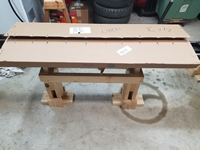
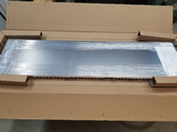
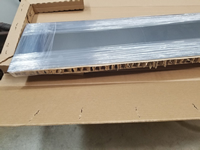
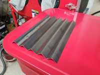
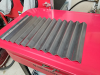
After searching for years for something that I could just purchase to use to replace the rusted-out tunnel rails on my chassis, I decided to just make my own. "Tunnel rail" is what I am calling the lip on the bottom of the tunnel where the tunnel bottom plate is welded and also where the floor pans rest on the tunnel. The closet thing I could find is a 15" tunnel section replacement that is made to replace the tunnel inside of frame heads. But they are around $35 each (plus shipping) and I would need at least 5 of those. Not only would this option be costly, but these aftermarket parts are way thinner metal than the original metal and the shape really doesn't match as well. I found that I could get a 12" x 48" x 2mm sheet of steel online for about $45 total, so I decided to purchase that and see if I could find a way bend it and make pieces to use. It came very well packaged and protected.
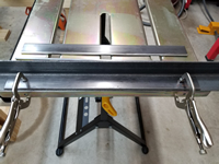
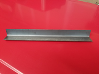
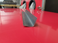
To bend the sheet metal and match the radius of the lip on the tunnel, I used two 18" long, 3/16" thick x 2" wide mild steel plates set at a 90 degree angle with a 1/4" round steel rod on the outer edge and welded them on the inside edge. This gives me a smooth rounded surface on which to pound the metal into shape. The sheet metal is 2mm thick and will take a lot of force to form it.
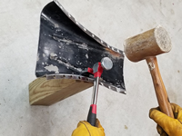
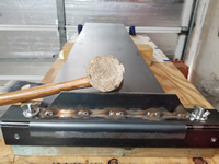
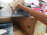
After the plates and dowel were welded together, I made a clamping plate, added clamping bolts, and mounted the unit on a 4" x 4" treated post. The post is dense and heavy and gives me something to hold on to when forming the shape. I used a large rawhide mallet to hammer it into shape. It was quite difficult to bend metal this thick without distorting it and to get it flat and even. With a lot of pounding, I was able to get it fairly flat and checked it against a tunnel section I had from a donor frame head. It matched well. The flange is longer than the tunnel flange, but it gives me more leverage to bend and form it and it can later be trimmed once the tunnel bottom plate is welded back on.
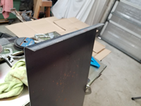
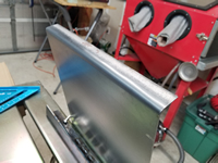
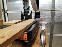
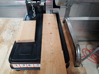
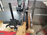
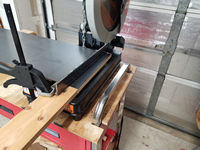
The next issue was how to cut the piece off and to get a nice, straight cut. I can't really do that well with an angle grinder with a cut-off wheel, so I decided to try to do this with my chop saw. I have an Evolution Rage 2 chop saw with a 14" multi-material blade that will cut steel, wood, and plastic. And although the blade is 14" in diameter, it doesn't go down far enough into the table to get a 12" long cut as I needed. So I took the clamping mechanism off of the table and attached a 1" x 4" piece of wood to raise the cutting area up and this made the cutting length about 12 1/4" which is sufficient. I then used some steel plate and 2 clamps to clamp the sheet down while cutting. It was a little difficult to make sure that the cuts were square, but I managed to get them close enough. I checked the first one against the tunnel and it matched well. I made another and it was very close to the first one. I made a few more and the results were good. I went ahead and made 12 of them. Good thing I did as I ended up using 11 of them to complete the tunnel.
Protecting Inside Of Tunnel Bottom Plate
by Garage Weasel on Nov.17, 2020, under Chassis
I decided to remove all of the factory's protective coating on the inside of the bottom tunnel plate. It was in very good condition with almost no rust damage there, which is surprising as this area was holding water for many years. The only area with damage was at the front end where it connects to the frame head bottom plate. Here, both had either rusted all the way through or had deep pitting.
After the protective coating was removed, I went over the inside area with a wire wheel on a drill. I masked off the sides where it will be welded back on the tunnel, and also masked the damaged area on the front end. The damaged area will be treated with a rust converter and I will make and weld on an extension to replace the rusted-through area. I then sprayed the inside area with Eastwood Matte Black Rust Encapsulator. This should protect it protected for a while. Once it is welded back on to the tunnel and all tunnel repairs are completed, I will recoat the inside of the tunnel again.


